Listed Mill Basement Conversion to Commercial Space
This substantial mill building was converted to residential and commercial space, Trace joined the design team and produced a detailed waterproofing design with associated reports to address a number of complexities including ingress from the adjoining canal lock and a retained/original baling press.

Minto & Turner Building waterproofing
Job type:
waterproofing

Grade II listed building
Requirement to provide totally dry space while preserving historic features including 1867 baling press
The mill above is being converted to apartments, so a structural warranty provider is on board, meaning that their requirements/approvals for waterproofing design and installation are a requirement
The structure suffered issues of water ingress associated with the adjoining canal lock, but could not be 'tanked' (listed) and we provided a creative solution
Four sump pump systems with eight pumps, eight discharge pipes and eight 60kg batteries (for power outage) were installed.
Original brick features retained in areas.


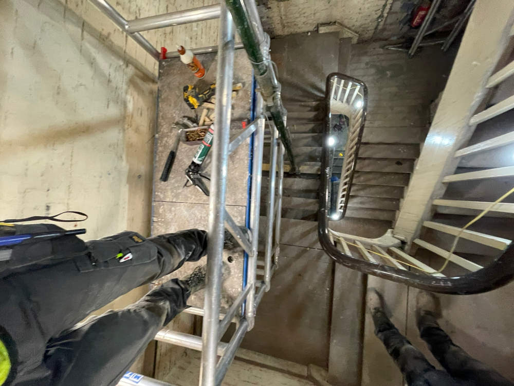
The Property
This was an unusual case in that 50% of the basement included a suspended timber floor, i.e. floorboards spanning between sleeper walls, with nothing but earth beneath.
This provides no actual floor structure to waterproof, and so a strategy for waterproofing was devised which included removal of the decayed timber and replacement with a concrete slab, bearing onto the sleeper walls with fill material beneath.
In listed buildings, systems must be sympathetic to what is a historic asset. Therefore, you cannot slap cementitious waterproof renders (for example) onto the inside of the structure, because it would bond to it, and this is considered irreversible damage.
As a result, reversible cavity drainage (cavity membrane, drainage channels, sump pump systems) waterproofing is the prefered option.


Type C - Cavity Drainage Waterproofing
Cavity drainage waterproofing is water management, you collect and remove penetrating water while isolating it from the interior so that it does not present an issue. There is reliance on the shell of the building to provide resistance to ingress, so that the cavity drainage system can deal with the volumes of water. If volumes of ingress are high, structures will often receive barrier tanking measures to reduce their permeability, but what do you do if it’s listed and you cannot use tanking to reduce substantial ingress?
This is what we had to design for here.
Part of the solution was to manage groundwater using land drainage. We observed the natural flow of water ingress prior to the concrete slab being laid. Part of the site externally falls away from the building (ground level reduces), and water ingress flowing along inside the building, drained out again local to where the external levels reduce.

Water management external of the structure
Therefore we installed land drainage in the oversite (below proposed slab), along the natural path of the water to encourage water to where it could exit. In addition to this, we added an extra sump chamber (single mains pump) with sealed/water-tight cover, which is detailed only to receive water if this backs up within the drain. If it does back up then the cover is sealed to maintain continuity of the structure/barrier to ingress, and internal of that is the true cavity drainage with 4x sumps (each with 2x mains pumps and a battery back-up system with multiple batteries). An interesting case requiring some well considered design and implementation to achieve low risk, working within the constraints of what was present.


We Are Approved & Accredited By